Wiring
Finally, we can begin installing all the wiring. Ā Work slowly and carefully through this process making sure to route the wires as cleanly as possible using wire ties or hot glue to secure them so as not to interfere with any moving parts.
Ā
Wiring the Power Supply
Before we can install the Logitech board, we must wire in the power supply.
Ā
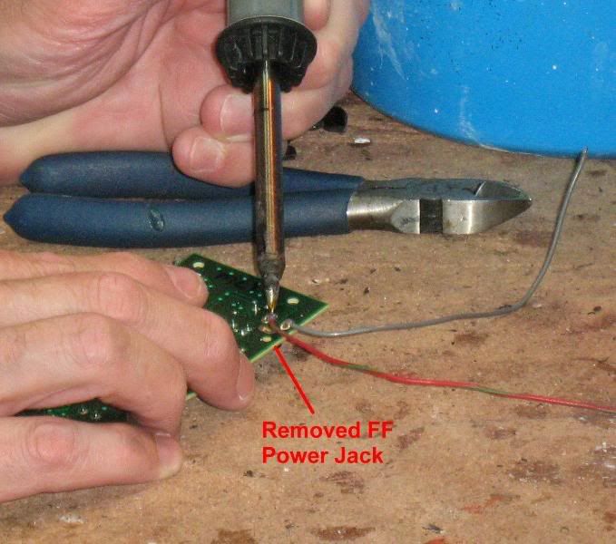
Solder a positive lead to the rear solder pod of the previously removed power jack on the Logitech board.Ā Then solder a negative lead to the solder pod closest to the edge of the board.Ā Study the picture carefully as getting these wires reversed can damage the circuit board.Ā
 Ā
ĀĀ
Ā
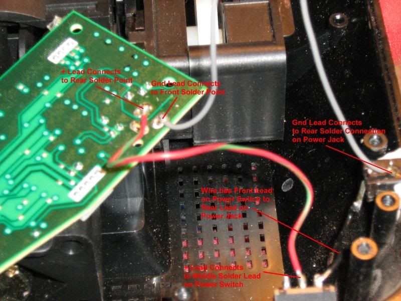
Next, solder a wire from the front lead on the Power Switch to the rear lead on the Power Jack (black wire in the picture).Ā Again, check the photo carefully and make sure you get it right. Ā
Ā
Then, connect the positive (red) wire from the circuit board to the center post on the Power Switch as shown in the photo.
Ā
Finally, solder the ground (gray) wire from the circuit board to the top lead on the Power Jack.
Ā
Carefully compare what you've done to the photo before continuing.Ā
 Ā
ĀĀ
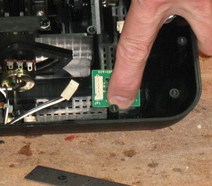
Before continuing, you'll want to test the circuit for power.Ā First, set the switch in the "off" position.Ā That will be the switch in the forward (facing the front of the joystick) position.Ā Next, plug in the 12V A/C adapter.Ā Put your finger over the voltage regulator chip on the circuit board.Ā (That's the one with the big copper area around it.) Ā Flip the switch to "on."Ā If you have the circuit wired wrong, this chip will get hot in a hurry.Ā If it gets hot, turn the switch off quickly.Ā Check your wiring. and repeat.
Ā
If all goes well, use a volt meter and check the voltage at the positive and negative posts on the circuit board.Ā You should get something close to 12 volts.ĀĀ
Ā
If everything checks out, disconnect the power supply and continue on.
Ā
Installing the Logitech and FighterStick Circuit Boards
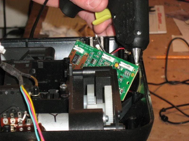
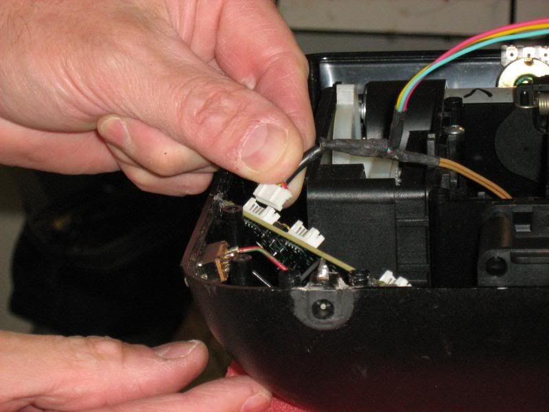
Straddling the corner where the Power Switch and Power Jack are, place the Logitech board as shown in the photo and place a dab of hot glue in the two top corners.Ā That will be enough to hold it in position.Ā Make sure the connectors have adequate clearance for the wiring harnesses.Ā
 Ā
ĀĀ
Ā
Next install the FighterStick between the two support posts in the front left (looking down into the bottom) of the base by squirting a bit of hot glue on the posts and holding the board against the posts until the glue dries.
Ā
Ā
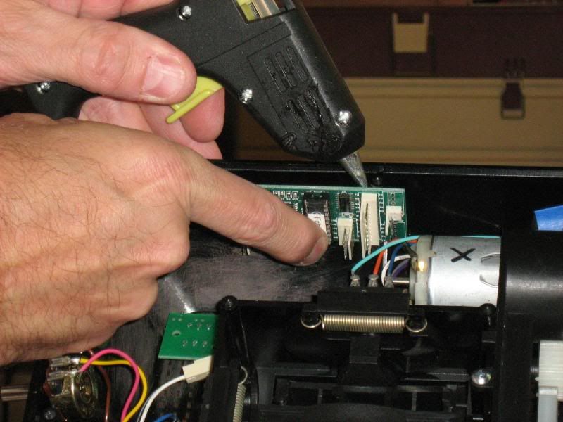
The last board to install is the Mode (LED) board.Ā Orient it as shown in the picture and put spots of hot glue in the corners to hold it in place.Ā
 Ā
ĀĀ
Ā
The Pots
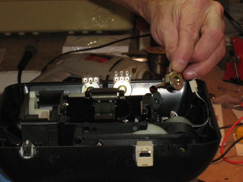
Take the three pots you removed from the FighterStick and slip them in the holes you drilled in the FX base.Ā Orient the terminals facing up (toward you).Ā Do not try to secure them in any way yet.Ā After you complete the wiring to these three pots, you will set them in place with some hot glue.
 Ā
ĀĀ
Ā
Connecting the Logitech Rudder and Trigger Wiring HarnessĀĀ
Locate the Logitech Rudder Pot and Trigger Wiring Harness and slip the two trigger wires in the gimbal stem from inside the base and out the top.
 Ā
ĀĀ
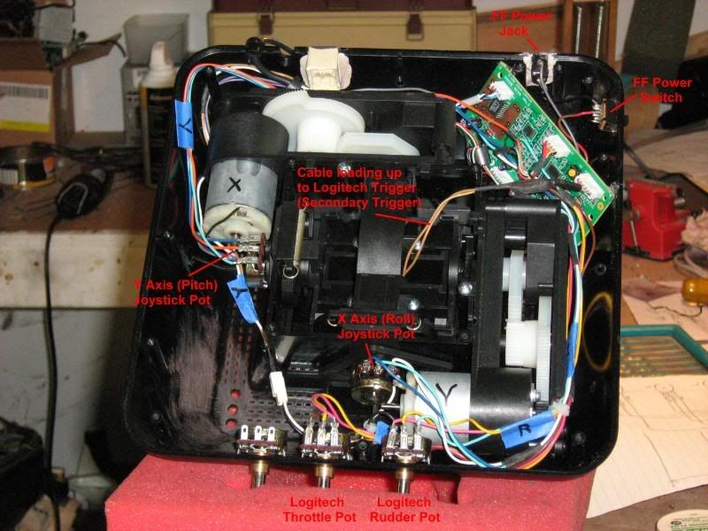
Next, connect the Rudder Pot connectors to the right most Pot on the front of the FX base.Ā
 Ā
ĀĀ
Finally, connect the wiring harness to the Logitech board (top right).Ā
 Ā
ĀĀ
Ā
Ā
Logitech Pots Hookup
Locate the Logitech Pots Wiring Harness.Ā
Ā
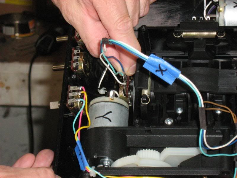
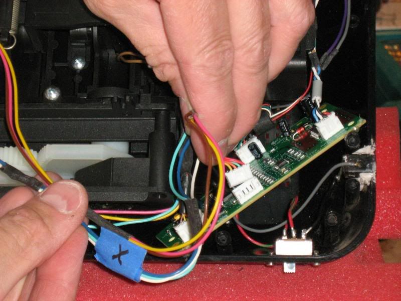
Plug in the X cable.Ā Be sure to consult the diagram so you get the order of the wiring correct.
 Ā
ĀĀ
Ā
Now do the Y cable.Ā
 Ā
ĀĀ
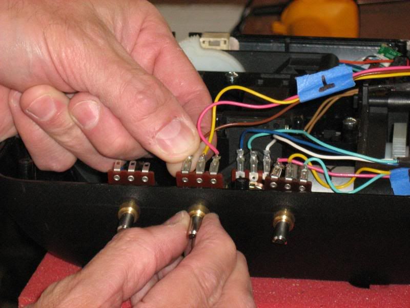
The last pot cable is the Throttle.Ā Connect it to the center pot on the base.Ā
 Ā
ĀĀ
Ā
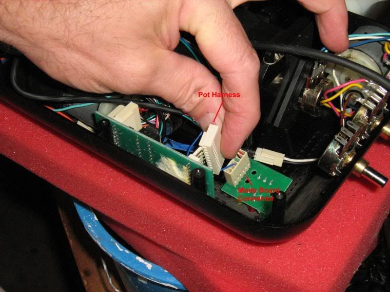
Finally, plug the harness into the Logitech board in the center connector.Ā
 Ā
ĀĀ
Ā
Motors Wiring Harness
Locate the Logitech Motors Wiring Harness.
Ā
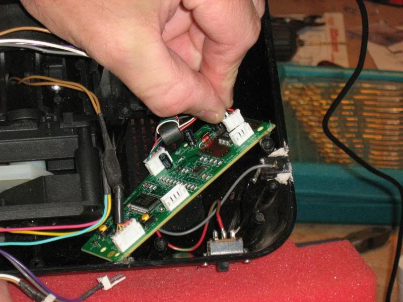
Plug the harness into the Logitech board (upper left corner).Ā
Ā
Ā
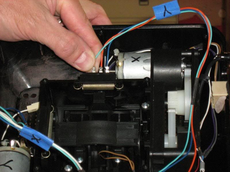
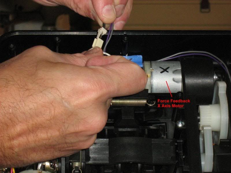
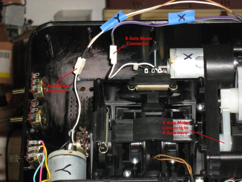
Plug in the X Motor connectorĀ
 Ā
ĀĀ
Ā
Connect the Y Motor plugĀ
Ā
Ā
Ā
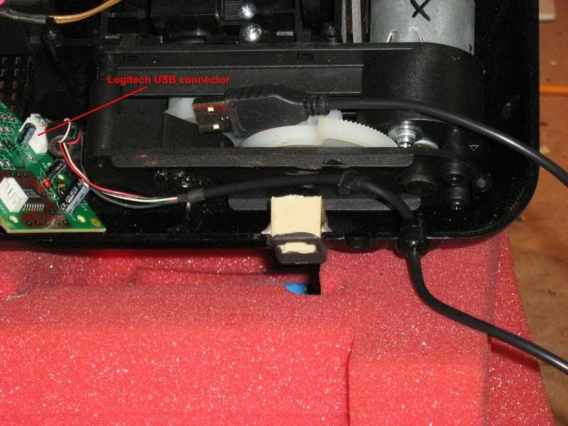
Logitech USB Cable
Plug the Logitech USB cable connector into the Logitech board (lower center) and route the cable out through the outer-most cable insert on the base.Ā You may need to supply your own cable relief if the built in one does not reach.Ā
 Ā
ĀĀ
Ā
Ā
That completes the Logitech circuit.Ā
 Ā
ĀĀ
Ā
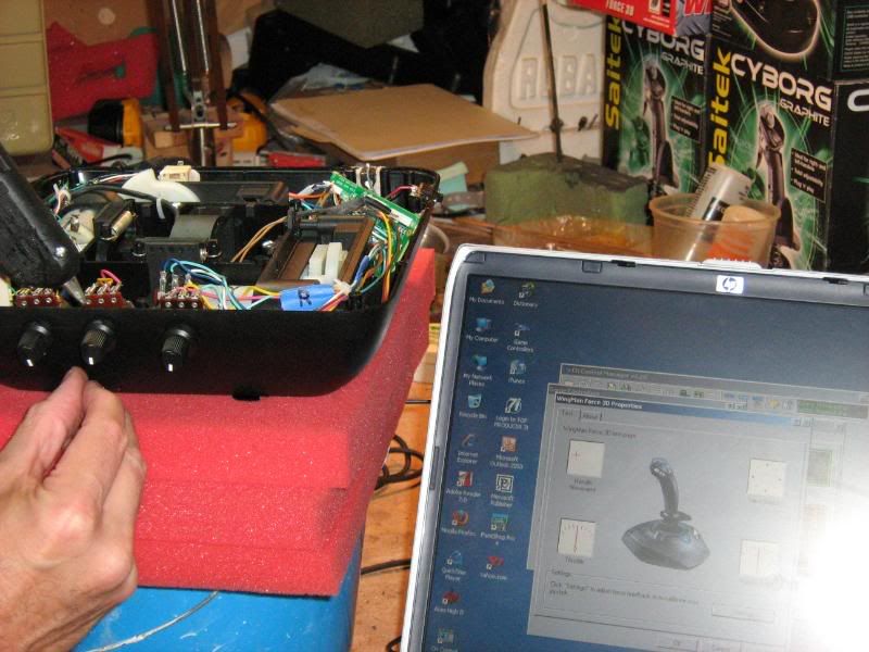
Before continuing, you should hook the USB cable up to a computer and check to make sure everything (except the trigger button which hasn't been connected yet) works properly.Ā Make necessary adjustments before continuing.
Ā
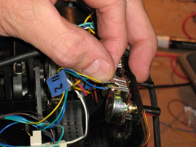
When you are satisified that everything is working correctly, go ahead and run a calibration then find the center points on the Throttle and Rudder pots and rotate the entire pot until the center pointer on the knob faces straight up.Ā When you get them lined up nicely, glue the pots in securely with some hot glue.Ā Be careful not to let hot glue get in the internal parts of the pot.
Ā
FighterStick Z Pot and Extension
Locate the FighterStick Z and Extension Wiring Harness.
Ā
Ā
Connect the Z Pot cable to the remaining pot on front of the base.
Ā
Ā
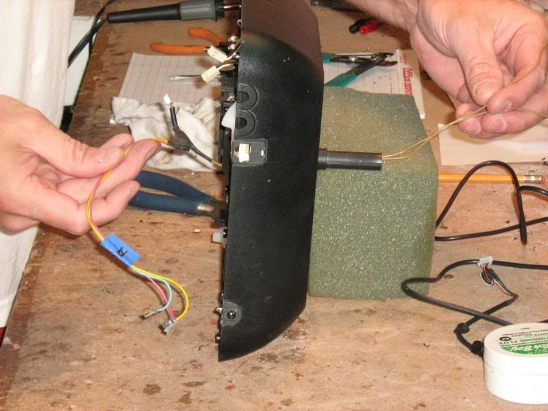
Next, plug the RJ-45 insert into it's case at the rear of the base.Ā Be sure it seats well.Ā Test it by plugging in a network cable and making sure it clicks in place correctly.Ā
 Ā
ĀĀ
Ā
Ā
Ā
Finally, plug the harness into the FighterStick connector (JS1) as well as the Mode (USB) board connectorĀ
 Ā
ĀĀ
Ā
Installing the Joystick Handle
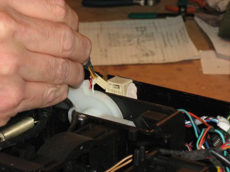
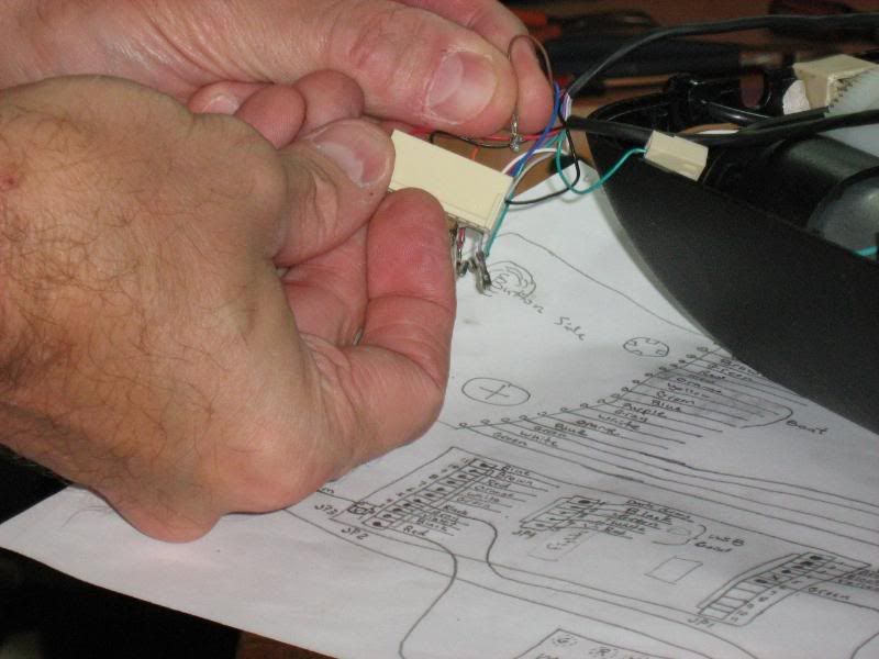
Locate a long piece of wire to use as a feeder and carefully tape the nine handle cable wires to it in such a way as it can be fed down through the gimbal stem (from the top of the stick base) so the cable can be reinstalled.Ā
 Ā
ĀĀ
Ā
Feed the cable back down into the joystick base.Ā
 Ā
ĀĀ
Ā
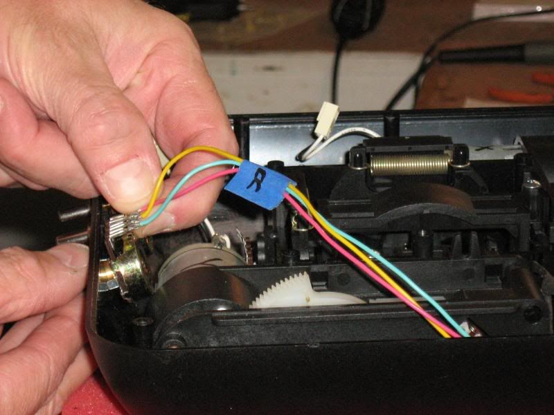
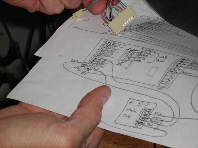
Carefully referencing the diagram, replace each of the nine wires back into the connector where they once were.Ā Be sure each one locks into place before moving on to the next one.Ā
 Ā
ĀĀ
Double check to make sure you've connected the wires correctly.Ā
 Ā
ĀĀ
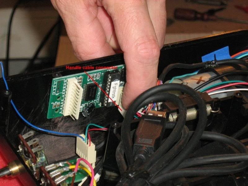
Plug the handle cable into the FighterStick circuit boardĀ
 Ā
ĀĀ
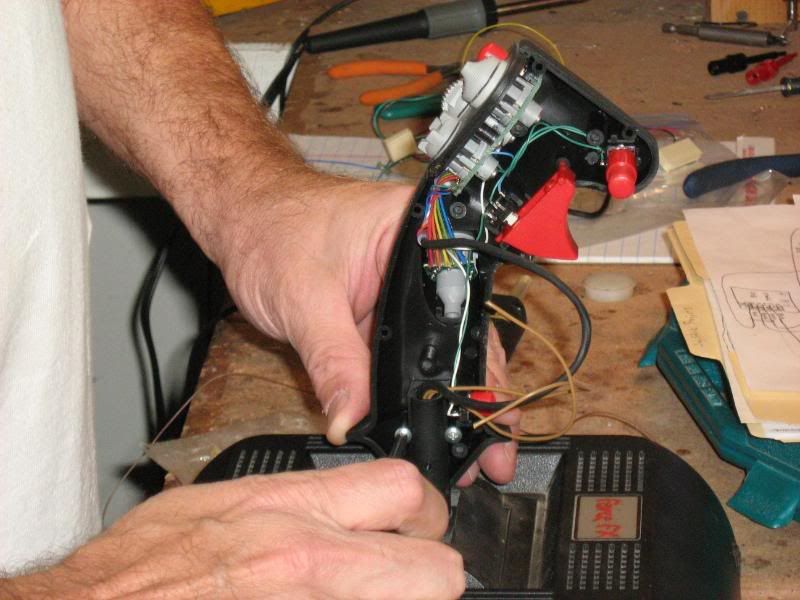
The joystick handle installation is complete once you secure the screws holding the handle to the stemĀ
 Ā
ĀĀ
Ā
Trigger Installation
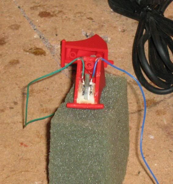
Build the Dual-Stage Trigger.Ā
 Ā
ĀĀ
Ā
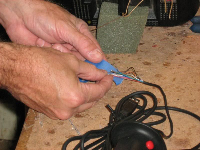
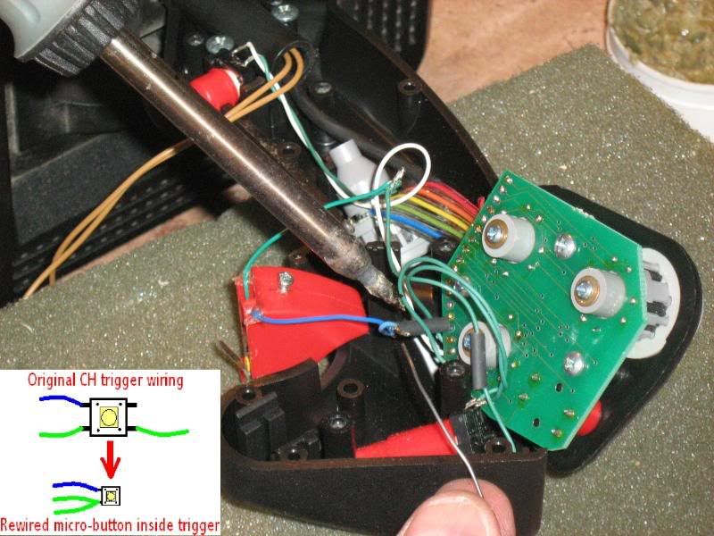
Solder the switch inside the trigger into the FighterStick circuit according to the diagram in the photoĀ
Ā
Ā
Ā
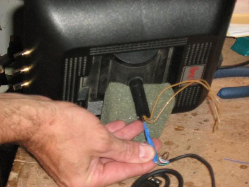
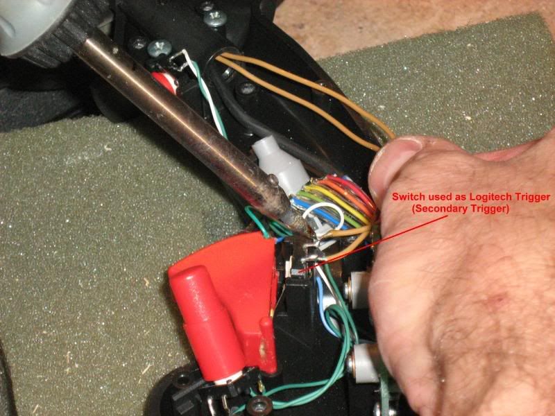
Next, cut the original trigger switch down as descibed in the Dual-Stage Trigger document and then solder it into place using the wires you fed earlier from the Logitech Rudder Pot and Trigger Harness.Ā
 Ā
ĀĀ
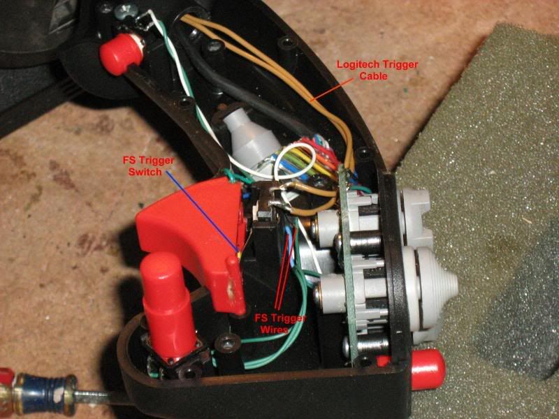
Finally, place the trigger into position and test to make sure both buttons function and that the spring returns the trigger correctly to its full open position.Ā
Ā
Ā
Final Testing
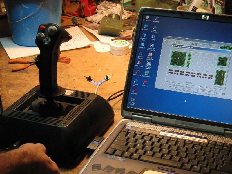
Before securing everything into place, plug in the FighterStick USB cable into a computer and test that all the hats and buttons work correctly.Ā Be especially careful to test the trigger as you have altered it the most.
Ā
Plug the test harness into the Extension Port and test to make sure the X and Y axes move correctly.Ā Remember, the FighterStick circuit no longer controls the joystick so nothing will happen when you move the stick.Ā The Extension Port pots have become the "joystick" with respect to calibration now.Ā
Ā
Ā
Once you have the FighterStick circuit working correctly, plug the Logitech USB cable in (do not unplug the FighterStick) and make sure both "sticks" work correctly together.Ā Test to make sure the dual-stage trigger functions as expected.Ā The FighterStick trigger should fire when you first squeeze the trigger followed by the Logitech trigger firing when you pull it in all the way.Ā
Ā
Plug in the A/C adapter and test the force feed back circuit.Ā Pull the trigger in all the way until the Logitech trigger fires.Ā You will get a gunshot sound and the stick should recoil back and return to center.Ā If it wants to jump off to the corner then the Motor Wires are reversed.Ā You can reach in and press the other couple of buttons on the Logitech circuit board as well as produce other effects.Ā