


Building Wiring Harnesses
Carefully building wiring harnesses to work with the FrankenForce will greatly increase the success of the project.Ā Wiring harnesses keep things orderly and keep the soldering iron away from the circuits as much as possible.Ā There are five wiring harnesses in the FrankenForce.Ā This chapter will cover the building each of these.
Ā
Here are the five wiring harness circuits that we need to build (the fifth one is the yellow shaded area of the FS Pots and Extension Harness):Ā
Ā
Ā
Ā
Ā
Ā
Ā
Ā
Ā
Ā
Ā
Ā
Ā
Ā
Ā
Ā
Ā
Ā
Logitech Rudder and Trigger Harness
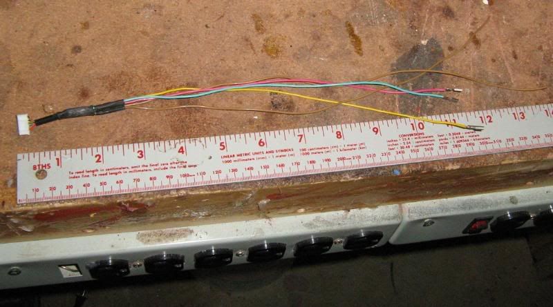
Cut the first inch or so off the Logitech J2 cable as that connector is used for this harness.
Ā
Ā
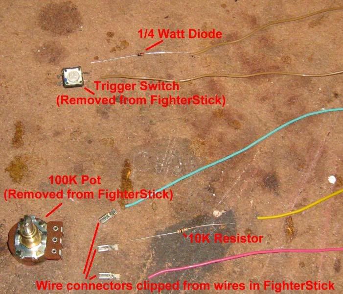
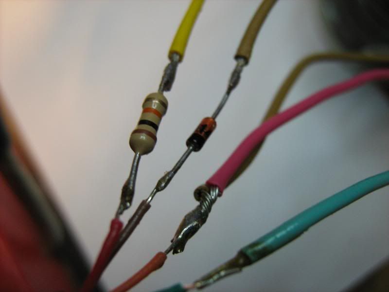
Solder the diode, resistor and the other wires to the the connector.Ā Use heat-shrink tubing to insulate all bare wires.Ā
Note:Ā Be sure to orient the black band on the diode toward the J2 connector.Ā
Ā
Ā
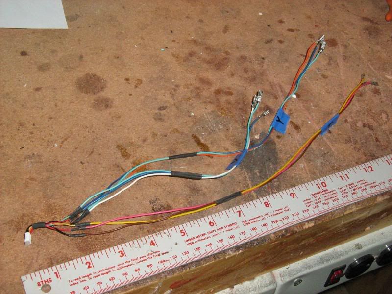
Cut the wires to the proper lengths as indicated in the wiring diagram and then solder the three wire connectors to the ends that will connect to the rudder pot.Ā
Ā
Ā
Ā
Ā
Logitech Pots Harness
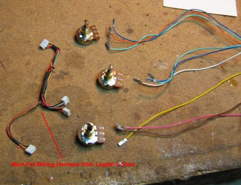
Cut the first inch off the J3 connector end of the original Logitech Pot Harness.Ā
Ā
Ā
Cut wires to length according to the diagram and solder all wires to the J3 connector.Ā Also solder the nine wire connectors to the pot wires.
Use heat-shrink tubing to insulate all bare wires.Ā
Ā
Ā
Ā
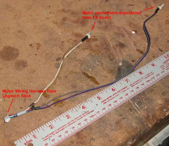
Logitech Motors Harness
Using the original Logitech Motor Wiring Harness and the two motor connectors removed from the FX circuit board, build the Motors Harness according to the wiring diagram.Ā
Ā
Ā
Ā
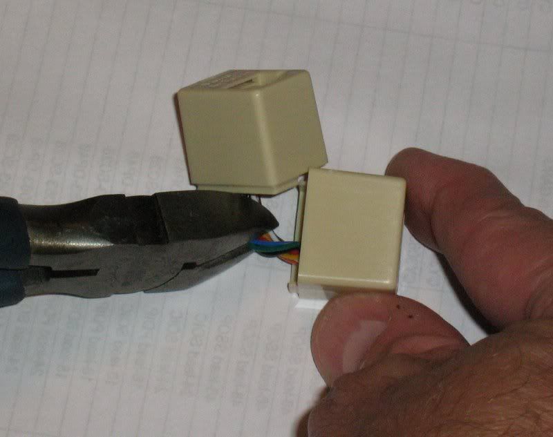
FighterStick Extension Harness
Pry the RJ-45 coupler apart to expose the internal wires.Ā Cut the wires as close to center as you can.Ā Using a jeweler's screw driver, remove the insert from one of the RJ-45 coupler halves.
Ā
Ā
Ā
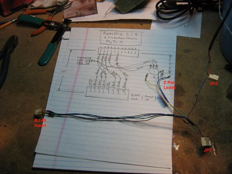
Using the FighterStick J1 harness, build the Extension Harness according to the wiring diagram.
Ā
Ā
Ā
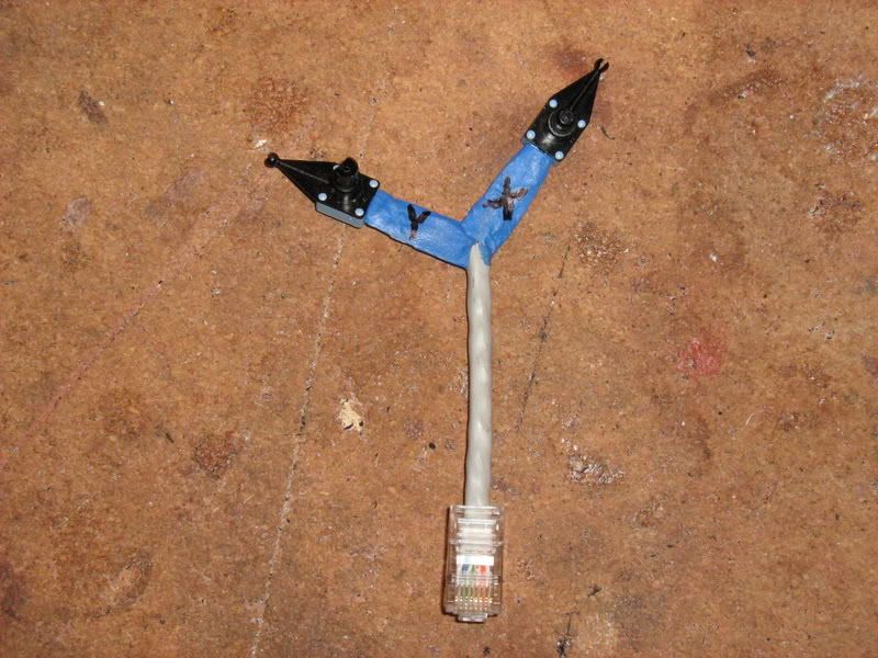
Extension Port Test HarnessĀ
I pulled two of the "so called" pots off the Logitech stick before I dropped it in the trash can to use for this test harness.Ā Cut the end off a network cable (RJ-45 plug) and wire it to the pots according to the yellow shaded portion in the diagram above.Ā
Ā
Ā
The next task is to make the modifications to the base of the FX stick