Preparing to Build the FrankenForce
Ā
We begin this project by looking at the overall plan for building the FrankenForce.Ā We take an inventory of everything you will need to accomplish the job.Ā Here is where you will decide what changes you want to make to the design and learn about all the extra features available to you.
Ā
Inventory
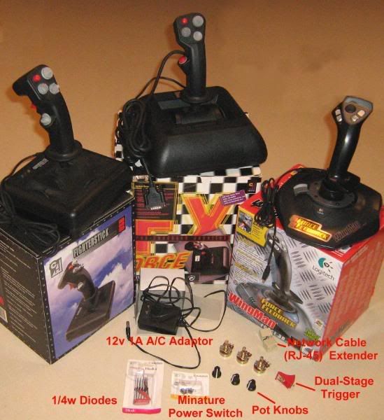
Here's what you need:
- 1 - CH Products FX stick
- 1 - CH Products FighterStick or CombatStick
- 1 - Logitech Wingman Force 3D stick
- 1 - 12 volt, 1 amp A/C adapter (typically used to power most network routers)
- Some 1/4 watt diodes.Ā You can find these at Radio Shack or similar store.
- 1 - 10K ohm 1/4 watt resistor.Ā Radio Shack has tons of these.
- 1 - Single pole/Single throw sliding switch.Ā Again, Radio Shack is a good source for this.
- 1 - RJ45 network coupler. Be sure you buy the type that will snap open (as you see in the picture below) to expose the internal wires.Ā You can find these at most stores that sell computer network supplies such as Cyberguys.
- 3 - 1/4" knobs for the extra pots installed in the base of the FX stick.Ā I found the perfect knobs at Guitar Nucleus.Ā They are Fender guitar amp knobs and come in a package of six.Ā Part number is GN0932KN-FEN6
ĀThe pots, wires, etc. can be salvaged from the left over parts from the three sticks.Ā
 Ā
ĀĀ
Modification Details
The FX is gutted of all its electronics.Ā All we keep are the FF motors, linkage, pots, etc.Ā The handle of the FX is replaced with the handle on the FighterStick.Ā The gimbal stem however of the FX is left intact as it is identical to that on the FighterStick.Ā The FX cables are a great source for all the multi-colored wires you are going to need for this project so you should cut the outer insulation away on these cables and pull the wires out of them.Ā Also, the three pots of the FighterStick should be removed and used for the three rotary controls mounted in the base of the FX.
Ā
The FrankenForce requires a different A/C adapter then the one that comes with the Logitech Wingman Force.Ā The reason is the motors in the FX run at half the voltage and require much more power then the dinky little things in the Logitech stick.Ā For best results, I recommend you stick with a 12v 1A adapter.Ā
Ā
The final chapter of this document addresses the various options for using the RJ-45 extension jack.Ā
Ā
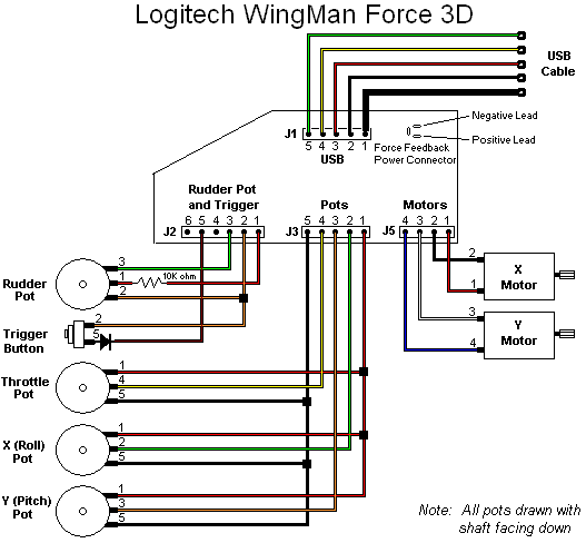
Logitech Circuit Layout
Here is the layout of the Logitech circuit.Ā Note that the trigger button, diode on pin 5, and the 10K ohm resistor on the rudder pot are actually on a second circuit board up in the handle of the joystick.Ā This second circuit board is not used as we provide our own button, diode and resistor just to simplify the fabrication.
 Ā
ĀĀ
Ā
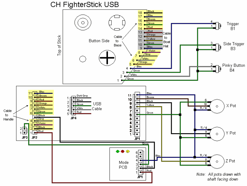
FighterStick Circuit Layout
This diagram shows the FighterStick circuit including the details in the joystick handle.
Ā