Digging Into TrackIR5
Beyond the Manual
The Journey
I, like so many other flight simmers have spent years
trying to escape the POV hat. My desire
for a more realistic viewing system began with the first TrackIR
where you put the little stickers on your forehead or the bridge of your
glasses. Although I have been tempted by
the alure of VR, I seem to always find my way back to
TrackIR. Having
begun with combat flight sims, the need for a fast viewing system and the
elimination of blind spots was paramount.
Then I drifted into general aviation and the need tailed off. I sold my TrackIR4 camera and upgraded to
TrackIR5 but since GA sims doesn't tax your viewing system that much, I basically
just plugged the thing in and used it right out of the box. Recently I've regained interest in air
combat causing me to dig into the details of version 5.
We flight sim enthuasists all
have various sized monitors, eye conditions, and tastes which makes
understanding how to configure your TrackIR set up an
important study. I now have a triple
monitor setup and wear progressive lens glasses which has changed my viewing
environment yet again. It should be a
goal for all of us to make our viewing system as comfortable and usable as
possible. Thus
the purpose of this document.
Read The Friggin Manual
The first place to start is a thorough reading of the
User's Manual: https://www.naturalpoint.com/trackir/documents/TrackIR-software-5_4_0-Manual.pdf which does a decent job of describing the
interface including the many rather daunting graph curves of the 6DOF system. This document will only address the
customizing of the 6DOF curves and other issues relating to flight simulation
as the manual does a good job on the other details.
After reading the manual and properly mounting the TIR
camera and your head tracking "antlers", it's now time to customize
the settings for your particular environment.
At first glance, you might be tempted to just ask for a friend's copy of
his TIR profile but that is generally a bad idea as hopefully you'll soon
understand.
Measuring Your
Environment
As previously stated, we all have various sized monitors
as well as varying degrees of tastes and eye health conditions. Because of this, it is important to take some
measurements. You should have already
set up your camera and TrackClip according to the
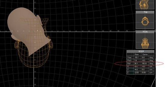
description in the manual. Make sure
when you are sitting comfortably in the "pilot's seat" that the TIR
camera reflects as reasonably close to the center of the Camera display as
possible:

Once
you are satisfied with placement, it's important not to make further
adjustments so as to nullify the measurements you will take. In reality, only two of the six axes rely
heavily on the dimensions of your viewing screens, yaw and pitch,
but these are the most important so we must be as accurate as possible to get
good results. There are two important
measurements that we will be looking at.
Both of these can be done with the TrackIR
Software and will give far better results than trying to use rulers or protractors. These measurements are: Maximum X&Y Points (i.e., your monitor
bezels) and Transitional X&Y Points. Each of these will be futher
explained.
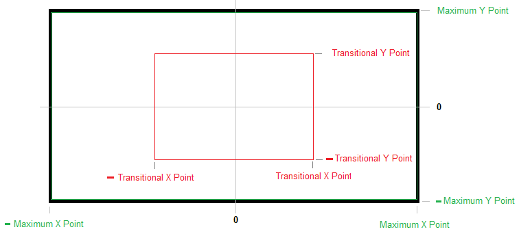
Maximum
X Point
This
measurement is typically the location of the right-hand bezel of your
screen (or right-most bezel in the case of multiple monitors). The left-hand X Point is simply the
negative of that measurement because the screen is symmetrical. Therefore, you only need to measure one side
of the screen. To get this measurement,
put on your "antlers" (with the TrackIR
Software running and tracking your head movement). Be sure the HUD windows are
active:

Sit
in the normal "pilot seat" with your feet on the rudder pedals, get
as comfortable as possible. Hold your
head as steady as you can and fix your eyes on the 0,0 point (from the
illustration above). Hold steady and center the TIR. Now, being careful not to tip your head
forward/backward or side to side, rotate your head slowly to the right until
your nose points right at the right-hand bezel of your screen. Holding your head as steady as a rock, move
your eyes over to record the Raw Yaw reading from the 6DOF HUD
window. You may find this easier
(especially if you have multiple monitors) if you grab the entire TrackIR window with your mouse and drag it along with you
as you move your head. You might want
to repeat the process a number of times and decide on an average value.
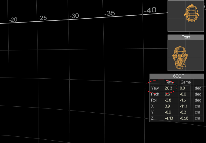
In
this example, using a single 27" monitor, I'm getting a reading of about
20 degrees:
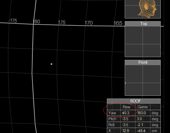
If
I use a triple-monitor setup (one 27" center monitor with 27"
monitors to either side), I'm getting a reading of about 50 degrees to
the edge of my right monitor:
Now,
repeat the process for the left edge of your viewing area just as a sanity
check. You should get about the same
value as the left side except that it will be the negative of the right
side. Record the value you decide on as
your Maximum X Point.
Maximum
Y Point
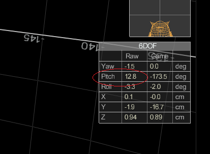
Using
the same technique, record the top and bottom edges of your screen as your Maximum
Y Point. Note that the Y dimension
will not change in a multiple-monitor configuration so long as all your
monitors are the same height.
In
the example with a 27" monitor, I'm getting about 13 degrees.
Transitional
X Point
This
measurement is the horizontal location where you feel most comfortable
beginning the transition from looking at the straight-ahead view and where you
want panning to begin. In other words,
as you look straight ahead at the screen and begin to move your head to the
side, the point where you would like the view to begin to move to the side
view, this is the transition point.
This is pretty subjective. To get
the idea, face the screen in the "pilot position" and begin to rotate
your head to the right and imagine where you feel the most comfortable with the
view beginning to change toward the right wing of your plane. With my three-monitor setup, since I have
such a wide view already (about 100 degrees of viewing area), I decided about
the 20 degree point was where I wanted TIR to begin moving my view
toward the right wing of my airplane.
With a single 27" monitor, it looks like around 6 degrees is
a comfort zone for me. Again, this is higly subjective and you might find you have to fly a while
and come back to this exercise to fine tune things.
Transitional
Y Point
Same
as before but you'll find that the Up and Down movements are greatly
compressed. I found my comfort Transitional
Y Point to be only about 1 degree from center in either direction.
Measurement
Summary
After
a number of attempts at this, I arrived at the following measurements:
Single
27" monitor:
Maximum X Point = 20 degrees
Maximum Y Point = 13 degrees
Transitional X Point = 6 degrees
Transitional Y Point = 1 degree
Three
27" monitors:
Maximum X Point = 50
degrees
Maximum Y Point = 13 degrees
Transitional X Point = 20
degrees
Transitional Y Point = 1 degree
Certainly,
the values you get will be different based on your monitors, condition of your
eyes, etc. Over time, I may change my
values several times as I get more comfortable with my configuration.
Learning
the Interface
TrackIR is a 6DOF system meaning there are
six motions your head is tracked while playing a game. Each of these six motions is represented by a
two-dimensional Cartesian plane mapping actual head rotation/movement
(horizontal axis) to in-game head rotation/movement (vertical axis). The actual head movement (horizontal axis) is
displayed in either degrees or centimeters (more about this
later) from the center (point where you center TIR) and the in-game head
movement is a multiplier (vertical axis) of the actual head movement.
The
TrackIR Software divides the interface into two
parts. The first part, Basic
Settings, is "global" control meaning these settings apply to all
profiles that you use. Here, you set
the Tracking Target to be the type of TrackClip
you have and the Motion Control is where you set your Speed and Smooth
settings. I'm not going to belabor
this further as you can read the manual.
What
is of most concern to us here is the Advanced Settings. In this section, we can create a profile, choose
hot keys for the TIR commands, set up head movement curves, associate specific
profiles to game titles, and configure camera settings. We will concentrate on manipulating the six
curves for a given profile.
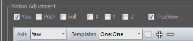
Before
we dive into the heart of TrackIR5, there are a couple of tips worth
noting. First, work on one axis at a
time and turn off the motion of all the other axes. If you are working on the Yaw axis, in
addition to selecting that axis, turn off all the others:
Don't
forget to turn all the axes back on before you go flying! I've done that more than a few times.
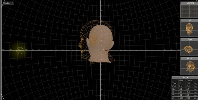
Another
handy aid is Display->Rear This will
show two heads, a solid one and a wireframe one. The solid head tracks your actual head
movement while the wireframe head tracks the in-game head. This is very handy for showing you the
effect your curve is having while you work on it.
You
can also jump back and forth between TrackIR and your
game using the Window Key. This
will allow you to make adjustments and then pop back into the game.
Motion
Curves
The
six axes (degrees of freedom) curves are classified into two types: "Head rotation" and "Head
movement". Of the "Head rotation"
types are Yaw, Pitch and Roll. In the Yaw axis you rotate your
head as if saying "No". In the
Pitch axis you rotate your head as if saying
"Yes". In the Roll axis
you rotate your head from side to side like a dog trying to understand
what you are saying. Of the "Head
movement" types are X, Y and Z. These axes do not involve rotating your head
but rather moving it while continuing to face the screen. In the X axis you move your
head left or right like you are trying to look around an object. In the Y axis you move your
head up or down like you are trying to look over or under an object. in the Z axis you move you head
in or out as if you are trying to look farther or nearer an object. The TrackIR
Software uses two types of coordinate systems for these two types of
curves. For the "Head
rotation" types, the X axis is titled "True Head Angle (deg)"
and the Y axis is titled "Rotation Speed (degs/deg)"
and is measured in degrees. For the
"Head movement" types, the X axis is titled "True Head Movement
(cm)" and the Y axis is titled "Head Speed (cms/cm)"
and is measured in centimeters.
Notice in the screen shot below, I've
created a profile named "homeboy-singleMonitor". I have selected Yaw as the only
movement in the Motion Adjustment section and turned off all other
axes. Also, I have turned on TrueView
on all my curves as it provides a more realistic experience. You can experiment with this and I think
you'll agree to turn it on for all your curves.

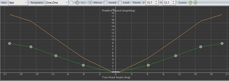
There
are a number of things to pay attention to in this graph. As described earlier, the Yaw axis is
a "Head rotation" type of movement so you will notice that the
horizontal axis is titled "True Head Angle (deg)" and the vertical
axis is titled "Rotation Speed (degs/deg)".
In
this screen shot, I have zoomed out all the way (click the scroll-wheel of the
mouse). Along the horizontal axis are
the numbers "-45, -30, -15, 0, 15, 30, 45" which correspond exactly
to the degree with which you move your head.
These are the degrees of actual head movement that TIR allows you to
configure. Therefore, the maximum screen
width that you can configure is 50 degrees (50 is not actually shown) from the
left and -50 degrees from the right for a total of 100 degrees of configurable
monitor area. That is not to say that
TIR will not manage a larger area; you just can't adjust values beyond those
points. Points further out than 50
degrees are extropolated from the last Control
Point (described later).
In
the vertical axis notice the numbers 0, 5, 10, 15, 20, 25, 30, and 35. These numbers correspond to in-game head
movement. They are multipliers
of the corresponding horizontal axis. That means that a point on the graph
where the True Head Angle is 10 degrees (moving your head 10 degrees) and the
Rotation Speed (multiplier) is 2 would produce a 20 degree (10 X 2) in-game
head movement. This relationship is what
gives you the ability of looking to your six o'clock position even though your
head is actually only turned 20 degrees to the side. Pretty cool!
TIR
provides 11 Control Points of curve configuration (more on this later);
five to the left, five to the right plus a center point. You can grab these Control Points and drag
them where you want them to configure your curve. You can also click on one of them and place
it precisely using the Point: X & Y coordinates.
If
you look closely you'll see three colored lines. The small red line
running vertically from the horizontal axis at the 9.8 degree
mark on the horizontal axis is the current head position. That means that my head was exactly 9.8
degrees to the left of center when I took the screen shot. When you center your TIR position, this line
will be exactly at the 0 position on the horizontal axis. As you move your head, it will reflect the
exact position (in degrees) on the horizontal axis. The green line
represents the in-game head position relative to the actual head position and
is managed by moving the Control Points around on the graph. Finally, the orange
line shows the result of applying the Speed and Smooth
values you have set in Basic Settings to the in-game line (green line).
If you set your Speed value to 1, the orange and green lines will merge
into a single orange line as there is no "speed" associated with the
curve. Notice the shape of my orange
line as a result of setting my Speed to 2.
You
will also notice a dashed line running horizontally across the graph. This is the "one-to-one" line. Points you place on this line will produce
in-game head movement that exactly match your actual head movement. That is, there is a 1:1 ratio between actual
and in-game movement for all points placed on this line. A point placed below this line will produce
"slower" in-game movement than actual. If you move a point all the way down to
zero, the in-game head will not move at all at that position regardless of
actual head movement. This line provides
a convenient reference to how far from actual head movement your curve is. If you had a curve that was exactly on top of
this dashed line then your curve would have no exaggerated head movement at all
and your in-game head would move exactly like your
actual head.
Creating the Curves
Now
that we have our measurements and a better understanding of graphing system, we
can proceed to configuring the six curves of the 6DOF system in TrackIR.
Yaw
As
a matter of habit, any time you choose to work on a particular axis, choose
that axis (Yaw in this case) from the Axis pull-down and then turn off all the
other axes so you can isolate just the one:

You
will use the 11 Control Points to define the behavior of the curve you
want for the axis being configured. You
will probably need to zoom in (roll the mouse-wheel forward or draw a box
around my curve), to reveal all 11 Control Points:
Look
closely and you'll see five points on the left of the curve and five on the
right with a center point right in the middle smashed close together with the
two inner-most points. Also notice that
the curve is symmetrical. This is
because I have turned on the Mirror switch. Having this switch turned on allows me to
just move a point on either side of the graph and the corresponding point on
the other side will "mirror" that movement. You will want Mirror
turned on when you are working with axes that you want to be symmetrical like
the Yaw curve.
Notice
that my middle three Control Points are right on the 0
multiplier line (vertical axis) and are very close together. If I zoom in real close on those three
points:

you'll
see that my center point is at (0,0) and I have the two adjacent points almost
at 0.5 degrees to either side of center.
Since the multiplier (vertical axis) is at zero, this creates a "deadzone" of 1 degree right at the center of
the screen. This allows me just enough
dead zone to keep my view steady as I'm trying to line up a shot on a target
without adversly disturbing the natural head
movement. You will see later that I use a deadzone of
a whopping 40 degrees with my triple-monitor setup! That is because I have such a wide-angle
view, I don't want any movement until I start to get beyond those boundaries
(more on that later).
Returning
to the previous screen shot, notice the Control Points on the left and right
extreme positions. Here is the zoomed
in view of the right most point (head movement to the far left):
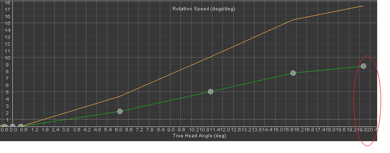 The horizontal position of this point is right around 20 degrees (looks
like between 19.8 and 20.4; hard to read as the numbers are jammed
together). Why did I place this point at
20 degrees? Remember the measurements we
did at the beginning of this document?
20 degrees was the edge of my display on a single 27" monitor. There is no reason to try to control any
points beyond that as they will be off the screen anyway. Any movement beyond this point will simply
be fluidly extrapolated by TIR. Besides,
we only have 11 points of control. No reason
to waste them on parts of the graph we're not even going to see. Now, do you remember measuring a location on
your screen we called Transitional X Point? Do you remember what that value was for the
single 27" monitor? Yes, it was six
degrees. This is the point where I
decided I wanted to see some "serious" head movement
translation. Therefore, I set a Control
Point at the 6.0 degree point with a multiplier of
2. This means when I turn my head six
degrees from center, my in-game head will be twice that at 12 degrees. Since I want to make sure I can turn my
in-game head all the way around to check my six (i.e., 180 degrees) within the
width of my screen (20 degrees), I set my last Control Point at 20 degrees with
a multiplier of 9. That means when my
head reaches the edge of the screen (20 degrees), my in-game head will be 20 x
9 = 180 degrees. I'm looking right at
the tail of my plane when my head is pointing at the bezel of my monitor. Since TIR will extrapolate, the view will
actually go beyond 180 degrees if I continue to turn my head. It starts to get uncomfortable to fix my
eyes with my head turned that far anyway so it's fine to stop at the bezel.
The horizontal position of this point is right around 20 degrees (looks
like between 19.8 and 20.4; hard to read as the numbers are jammed
together). Why did I place this point at
20 degrees? Remember the measurements we
did at the beginning of this document?
20 degrees was the edge of my display on a single 27" monitor. There is no reason to try to control any
points beyond that as they will be off the screen anyway. Any movement beyond this point will simply
be fluidly extrapolated by TIR. Besides,
we only have 11 points of control. No reason
to waste them on parts of the graph we're not even going to see. Now, do you remember measuring a location on
your screen we called Transitional X Point? Do you remember what that value was for the
single 27" monitor? Yes, it was six
degrees. This is the point where I
decided I wanted to see some "serious" head movement
translation. Therefore, I set a Control
Point at the 6.0 degree point with a multiplier of
2. This means when I turn my head six
degrees from center, my in-game head will be twice that at 12 degrees. Since I want to make sure I can turn my
in-game head all the way around to check my six (i.e., 180 degrees) within the
width of my screen (20 degrees), I set my last Control Point at 20 degrees with
a multiplier of 9. That means when my
head reaches the edge of the screen (20 degrees), my in-game head will be 20 x
9 = 180 degrees. I'm looking right at
the tail of my plane when my head is pointing at the bezel of my monitor. Since TIR will extrapolate, the view will
actually go beyond 180 degrees if I continue to turn my head. It starts to get uncomfortable to fix my
eyes with my head turned that far anyway so it's fine to stop at the bezel.
In
summary, let's go over the seven Control Points we see in this last zoomed in
screen shot:
The
left most point we can see is at -0.6 degrees (hard to tell that). This is the left most point of my
center-screen dead zone.
The
next point is my center point. It is
right on (0,0).
The
next point is at (0,0.6). This is the
right most point of my dead zone. That
gives me 1 degree of dead zone on my Yaw axis.
The
next point is at (6,2). That translates
an actual head movement of six degrees to in-game of 12 degrees (x2).
The
next point is at about (11,5). That
translates an actual head movement of about 11 degrees to in-game of 55 degrees
(x5).
The
next point is at about (16,8). That
translates an actual head movement of about 16 degrees to in-game of 128
degrees.
Finally,
the last point is at (20,9) which we've already discussed gives us 180 degrees
at the edge of the screen (20 degrees).
As
you can see, the view speeds up as you get close to the edge of the screen and
is slower near the center. This provides
for a very comfortable and less "twitchy" head movement while
allowing the range of motion we need to look all the way to the rear. Also, since the points are the same on both
sides of the curve, the head movement will by symmetrical; just what we need
for a Yaw movement.
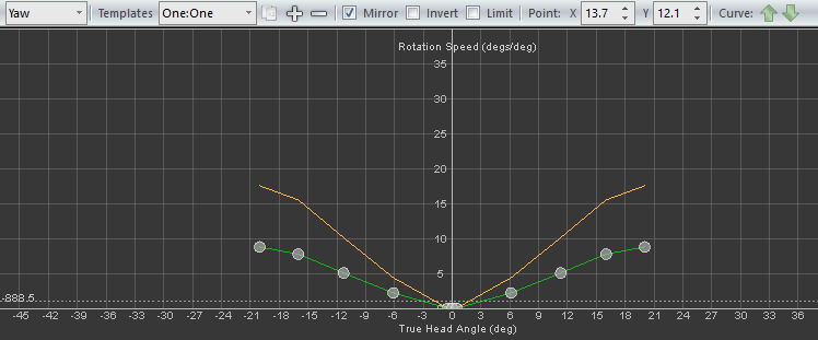
Here
is the Yaw axis for the single 27" monitor:
Here
is the Yaw axis for the triple-monitor setup using identical 27" monitors:
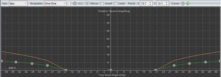
Let's
make some observations about the triple-monitor Yaw graph.
Notice
the very wide dead zone. 40 degrees! That's because I determined that my
Transitional X Point was 20 degrees so I didn't want any head movement at all
until my head was about 1/3 into my side monitors. This allows me to look around very naturally
within the viewing angle my monitors allow without TIR moving my view. Very natural; very comfortable.
Since
I measured my Maximum X Point to be 50 degrees, I set my last Control Point as
far as TIR allows with a multiplier of about 6 (about 300 degrees) which means
I achieve a rear view well before my head reaches that outside bezel (around 36
degrees, that second point up on the green curve). That's a pretty good stretch so I didn't
want to have to turn my head quite that far to get my six o'clock position. Trial and error revealed this to be a pretty
comfortable configuration. It's an example of starting with a calculated
configuration and then modifying it with experience.
The
Yaw axis is the only curve that needs to change between a single monitor setup
and a multi-monitor (e.g. triple-monitor) if all monitors have the same
dimension in the vertical axis. The
other five DOFs have no relation to the width of the display.
Pitch
Like
Yaw, Pitch is another of the "Head Rotation" type of curve so it's horizontal axis is titled "True Head Angle
(deg)" and the vertical is "Rotation Speed (degs/deg)". In this graph, as you move your head up, the
head position marker (red line) moves to the right on the horizontal axis. This axis is graduated in degrees of movement.
Here
is the Pitch curve:
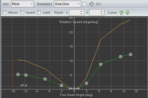
Since
my Maximum Y Point was 13, my graph doesn't go much beyond that point. My Transitional Y Point was 1 degree so I
started a pretty decent curve up to that first green point at 3 degrees. That's a good slope and feels very
comfortable.
Note
that this curve is asymmetrical. That's
because I determined that I wanted to have more "up" movement than
"down" because looking down need not go much beyond 90 degrees
(looking down into the cockpit or looking down over the edge of the cockpit
doesn't need that much. However, I
wanted to look up and actually look all the way back 180 degrees so I could
check my six by looking up in addition to yawing to my six. I like this a lot! At first it seemed weird but it's actually pretty
nice to be able to look behind me in more than just Yaw.
It's
also worth noting that Yaw and Pitch are the only two axes that rely on the
Maximum and Transitional Points in any way.
All the other axes are pretty much natural movements that you would
normally do inside a real cockpit.
Roll
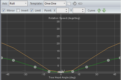
A
lot of people turn this axis off.
That's a shame. If configured
incorrectly, this axis can create a lot of movement that is really unpleasant
and it's easy to just turn it off out of frustration. However, if you get this set up well, it
really does help you deal with blind spots like trying to look around the
head-rest in the P-51. I worked very
hard getting this to work and this curve really does the job. The real magic of this curve takes place
inside the middle three degrees. Let's
zoom in and take a look at those Control Points at the center:
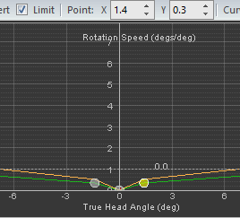
All
three of these Control Points are well below the 1:1 line so in-game head
movement is much slower than actual head movement in this region. Notice that the curve stays below the 1:1
line all the way out to the 6 degree point. That keeps movement really slow for much of
your viewing area. Before I took the
screen shot, I clicked on that right Control Point so you can see its coordinates. At the 1.4 degree
point on the Head Angle axis, the in-game head has only rotated 1.4 X 0.3 =
0.42 degrees. Even at the 6 degree point, the in-game head has just begun to catch up:
6 X 1 = 6 degrees. I also wanted to
eventually get 180 degrees of rotation so I accelerated the curve all the way
out to the 50 degree point. We achieve 180 degree
roll with this curve at around the 36 degree point:
X
The
X axis is a side-to-side movement as if you were trying to look around an
object. The remaining three axes (X, Y,
and Z) are "Head Movement" types rather than "Head
Rotation" types. The horizontal
axis is titled "True Head Movement (cm)" and the vertical is titled
"Head Speed (cms/cm)". The important difference between these types
and the ones we've looked at so far is that the movement is measured in centimeters
instead of degrees.
Here
is the X curve:
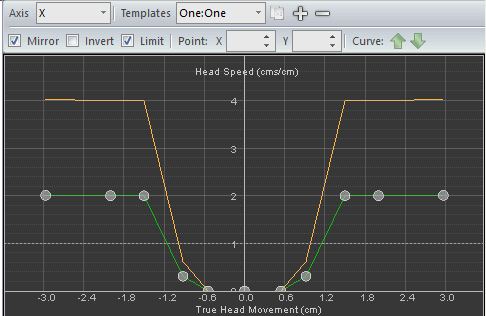
As
you can see, I've had to zoom way in to actually see this curve. It is really tiny. The entire width of the curve is a mere 6
centimeters and that includes a full one centimeter of dead zone! It does accelerate rapidly but the movement
never exceeds 2X. This, together with
Roll and Y provide a very natural and smooth ability to look around things
(like the P-51 head-rest and canopy struts).
The key to this axis, like Roll, is to keep the movement small!
Y
This
axis allows you to look over things and to look under things. With this axis, you can stretch your head up
over the instrument panel and see a little of the nose of the plane or stretch
out as you move you head over (X axis) and roll (Roll axis) to see around that
head-rest in the P-51. This axis allows
you to look up over the yoke to get a better view of the row of switches that
it is otherwise blocking. Also, you can
compress your neck slightly to get sight of that parking brake that is just out
of view under the instrument panel. The
Y axis completes the picture together with X and Roll in overcoming blind
spots. None of these three axes involve
very much movement at all (and they are all but useless in and of themselves)
but they work together beautifully to give you that very natural feel that we
all long for in a viewing system. I am
very excited to discover how to actually use these three axes.
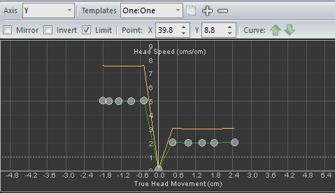
As
you can see I've had to zoom way in to even see the
graph. Notice the asymmetry. I made this graph asymmetric because it is
much easier to raise your head up (stretch out your neck) than it is to lower
it (compress your neck). I made the
in-game movement over twice as accelerated in the down direction than in the up
direction. This asymmetry makes the
in-game head move up and down in a pretty symmetric fashion. With all that said however, the movement is
pretty tiny; less than 5 centimeters total.
As with X and Roll, smaller is better!
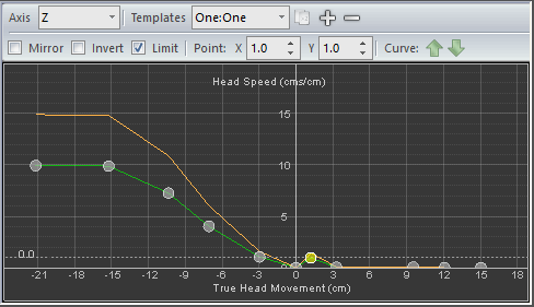
Z
Ok,
the final curve! The Z axis is basically
a zoom axis. It's what you use when
sitting in a darkly lit restaurant and you push your head into the menu so as
to see those tiny numbers and dollar signs.
In the cockpit, the Z axis is necessary to allow you to look closely at
the altimeter while you dial in a barometric pressure or zoom in on the piper
in a fighter. Any time you need to
"take a closer look", you need the Z axis.
I
decided that I don't really care to zoom out much as I find this axis pretty
much a "zoom in" sort of animal. Therefore I made it
asymmetrical with almost nothing in the "zoom out" direction. I set a point on the 1:1 line at (1,1) but
then disable zoom out movement altogether at 3 centimeters. This gives me a tiny bit of zoom out (I'm not
sure why really; didn't want to totally waste the ability I guess) but, as you
can see, I have a fairly healthy "zoom in" capability. It works great when looking down a piper so
much so that I haven't even used my "weapon zoom in key" since I set
this up.
Final Thoughts
I
was so excited with the results of an exhaustive study of TrackIR5 that I felt
I had to write this document; not only to share but to remember what I'd
learned. One of the most exciting
discoveries was the relationship between the X, Roll, and Y axes. After realizing the need to keep these
movements very small, my viewing setup came alive! As I am getting older and my eyes are
changing some since the early days of using TIR, it occurred to me how different
this system will need to be for other users.
The types and amounts of monitors used will also demand a highly
customized configuration as well.
Ever
since those days of struggling with the POV hat switch on my joystick and
saying every time I used it "there has to be a better way", I have
been seeking a more natural, fluid, and realistic viewing system that overcomes
blind spots. TrackIR5 is not there yet
but with a careful scientific configuration followed by
"seat-of-the-pants" tweaking, it's worth the effort put into making
it work.